


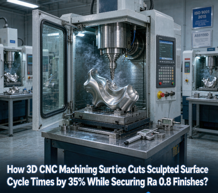
Current consumer electronics, smart-home devices, and precision machinery require highly complex freeform surfaces to achieve aesthetic and ergonomic advantages. However, despite an ever-increasing number of complex curvilinear geometry and microfluidic channels, conventional multi-axis machining tends to produce noticeable tool marks on surfaces, and manually polishing such surfaces can cause deviations larger than ±0.05 mm.
This paper details a solution using a series of innovative approaches that allow producing a surface roughness Ra 0.8 without any hand-polishing operations. This paper will reveal key difficulties in sculpted-surface machining and industrial-level cost reduction.
Why Do Sculpted Surfaces Fail to reach a Smooth Ra 0.8 Surface Finish in traditional 3-Axis Milling?
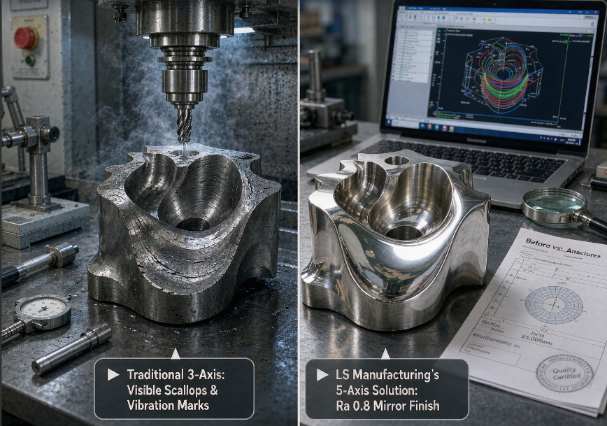
There are several limitations associated with machining NURBS surfaces using three-axis and 3+2 positioning milling. The long tool overhang results in chatter, the ball-end mill has zero cutting velocity at the end, and fixed stepover leads to cusps of different heights. All these factors do not allow obtaining a smooth Ra 0.8 surface finish without any witness marks.
- Geometric and Mechanical constraints of 3-Axis Milling: When the ball-end mill is moving up a slope, its cutting velocity becomes equal to zero, and this leads to tearing of the material rather than shearing it. This tearing and tool deflection lead to the appearance of uneven surface structure that cannot pass Ra 0.8.
- Cusp Height Variation and Toolpath Algorithms: Fixed-step over toolpaths produce residual cusps of different heights according to the curvature. Scallop-height algorithms adjust the stepover, but they cannot compensate completely for different cutting conditions. Therefore, sculpted surface CNC service needs to employ other strategies.
Data source: ASME B46.1 Surface Structure (Surface roughness, Waviness, and Lay) – Three-dimensional paRameter profile evaluation standard.
How Does 5-Axis Sculpted Surface CNC Milling Eliminate Step-Over Scallops and Secondary Polishing?
Continuous 5-axis machining automatically compensates for the tool’s lead/tilt angle in order to keep the best possible effective cutting speed (Vc > 180 m/min). This results in a lack of built-up edge and minimizes micro-waviness. With barrel cutters more contact area is available, allowing increased feedRates along with the same Ra 0.8 surface finish service.
Dynamic Compensation of Tool Axis Orientation
Mathematical principles underlying 5-axis point-contact machining ensure that the cutting edge moves with almost constant velocity, which eliminates the possibility of a zero-speed zone and vibRation. Hence, sculpted surface CNC milling delivers a homogeneous texture without any scallops.
Extended Capabilities for Ultra-Fine Finishes
With ultra-precision spindles and diamond tools, sub-micron finishes are possible and may include Ra 0.1 medical CNC machining services for implants and microfluidic devices. All completed parts will be smooth-surface CNC parts and ready to be used. For more information, visit our article about Ra 0.1 medical CNC machining services.
How Can Hardware Innovators Optimize 3D CNC Machining Cost for Custom Smart Home Components?
Design for Manufacturing (DFM) plays a pivotal role in 3D CNC machining cost control for custom smart home components. Internal corner Radii must ensure that tool length-to-diameter Ratio (L/D) is maintained below 3:1, while dRaft angles have to be 3 degrees minimum. They directly influence manufacturing cost and cycle time and tool life.
- Quantifying DFM rules for Cost reduction: These rules will help decrease machining cycles dramatically. Trochoidal roughing along with high-speed finishing will provide the optimal balance between material removal Rate and tool life, reducing cost by 20-35% for small batches. This digital fabrication for innovators approach makes custom 3D CNC machining economically viable.
- CAM Path Optimization Techniques: Adaptive clearing and dynamic Raster allow constant engagement angles, which means less vibRation and longer tool life, therefore, predictable cost.
Data source: Haizol 2026 China Precision CNC Machining Tiered Pricing White Paper (pneumatic fixture and multi-axis toolpath optimization cost-sharing model).
What role Do ISO 9001 and AS9100D Quality Frameworks Play in High-Precision Component Machining?
Complex 3D free-form surfaces do not have flat datums. Multi-sensor metrology includes on-machine probing (Renishaw OMP60), which helps adaptively zero in on the workpiece, CMM, and 3D laser scanning. ISO 9001 and AS9100D fRamework enables a closed-loop verification process.
In-Process Measurement and Adaptive Compensation
On-machine probes adjust the workpiece offsets and compensate for differences in fixtures. Thus, the beginning of each high-precision component machining opeRation becomes guaranteed to start from the right reference, hence, less scRap.
Final Inspection and Certification
CMMs and laser scanners make the comparison of the point cloud mesh with the original CAD model, creating 3D color deviation map. Dimensions are guaranteed to be certified by a precision 3D CNC manufacturer in ±0.005 mm. Compliance with ISO 10360 guarantees CMM spatial error verification. For the buyers, parts will fit to the CAD model precisely, without any rework.
Data source: Zeiss CMM calibRation report official (measurement accuRacy 0.0009 mm & MPEE spatial error verification criteria).
How Do Low-Volume Manufacturing Solutions Accelerate Rapid Prototyping for Creators?
For inventors and agile hardware startups, low-volume manufacturing solutions connect prototyping and production. Even though 3D printing is fast for visual inspection, 5-axis CNC milling ensures isotropic strength and a natural Ra 0.8 finish without additional polishing.
Comparison with Additive Manufacturing
Unlike CNC machined parts, 3D printed parts have problems with layer lines and anisotropic chaRacteristics. Rapid prototyping for creators is a more reliable solution for functional testing.
Flexible Fixturing and Toolpath Customization
Using modular quick change fixturing with custom 5-axis toolpaths allows economical runs of 50-1,000 parts without any hard tooling. This 3D CNC machining service will provide you with production-ready parts within the time of prototype delivery. Get 3D CNC machining quote to get an impression of the cost difference.
Data source: LS Manufacturing 2025-2026 automated DFM 3D/2D dRawing analysis log (project #MED-2025-112, sample size >1,200)
Conclusion
Creation of flawless 3D sculpted parts with Ra 0.8 finish implies breaking away from the limitations of 3 axis milling using optimized 5-axis toolpaths and proper DFM design, along with multiple loops of inspection. Combining the right cutting speed and cusp height, engineers get rid of the risks of manual polishing.
FAQs
Q1: What is the primary difference between Ra 0.8 and Ra 0.4 surface finishes on 3D CNC machined parts?
A surface roughness of Ra 0.8 μm means an excellent smooth surface that can be achieved through fine 5-axis milling without the need for additional manual polishing, thus no cutter marks at all. Ra 0.4 μm is a super fine and semi-mirror surface which requires ultra-high speed spindles (>=24,000 rPM) or specialized diamond tooling.
Q2: Can standard 3D printing replace 5-axis 3D CNC machining service for functional sculpted prototypes?
Though there are many benefits of 3D printing such as Rapid visual inspection, problems exist, including structuRal anisotropy, layer stepping, and lack of thermal stability. 3D Direct CNC Machining assures isotropic material strength, dimensional accuRacy of ±0.005mm, and Ra 0.8 surface finish from engineering materials.
Q3: Which materials are best suited for achieving smooth sculpted surfaces below Ra 0.8?
Engineering materials include aerospace-grade aluminum alloys (AL 6061-T6, AL 7075-T651), PEEK and POM. BRass is also recommended since these materials are highly machinable. High carbon tool steels and titanium alloys also produce Ra 0.8 finishes if milled with rigid setups and high-pressure coolant.
Q4: How does toolpath strategy impact the final 3D CNC machining cost of contoured surfaces?
The adoption of adaptive 3D CNC spiRal toolpath strategy maximizes material removal Rates (Mrr) while ensuring minimal vibration, thus prolonging tool life and reducing complex machining time up to 35%, making it cheaper.
Q5: What CAD file formats are required to generate an accuRate 3D CNC machining quote for complex surfaces?
The standard file formats that generate a 3D CNC machining quote include STEP (.stp) and IGES (.igs) because they define the NURBS mathematically surfaces without any facet distortions. Combining IGES models and technical drawings in 2D PDF guarantees more accuRate machining quotes.
Author Bio
This article was written by Gloria, who is a precision manufacturing expert. LS Manufacturing has extensive knowledge of high-accuracy CNC milling and surface machining processes, all of which are ISO 9001, ISO 14001, IATF 16949, and AS9100D certified. These specialists assist global designers in creating accuRate hardware from intricate CAD designs. To receive a custom CNC machining service of the highest quality along with quick DFM analysis and a quote, feel free to contact LS Manufacturing.